Experiment 3 (b) : To verify the laws of combination (parallel) of resistances using a metre bridge.
Aim :
To verify the laws of parallel combination of resistances using meterbridge.
Apparatus Required:
a) Metrebridge.
b) Two resistance wires.
c) Resistance box.
d) One-way key.
e) Jockey.
f) Galvanometer.
g) Battery eliminator.
Theory:
A meterbridge works on the principle of Wheatstone's bridge. According to this principle of four resistances P, Q, R, S are connected & formed a closed network ABCD & a cell is connected between A & C, then galvanometer will show no deflection when bridge is balanced. To get balanced condition, P, Q, R & S should be adjusted.
In balanced condition
$\frac{P}{Q} = \frac{R}{S} \quad \text{— (1)}$
If unknown resistance 'X' is connected in the right gap of meterbridge & null point is obtained at a distance 'l' from left end of meterbridge.
then Q is considered as X
R is considered as l
Hence, R will be considered as (100-l).
So equation ① becomes,
$\frac{P}{X} = \frac{l}{100-l}$
$\implies X = \frac{(100-l) P}{l} \quad \text{— (2)}$
If two resistances R_1 and R_2 are connected in parallel, their equivalent resistance is given by
$\frac{1}{R_P} = \frac{1}{R_1} + \frac{1}{R_2}$
$\implies R_P = \frac{R_1 R_2}{R_1 + R_2} \quad \text{— (3)}$
Procedure
a) A connection was made as per the circuit diagram.
b) The resistance wire is connected in the right gap.
c) Introducing a suitable resistance in the resistance box, jockey was touched at points near end A & end C.
d) If deflections were in opposite directions, the connection was correct.
e) Now choosing suitable resistance from resistance box, null point was obtained.
f) Values were recorded in an observation table.
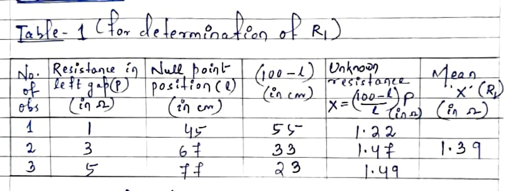
g) Value of 'X' was calculated in each case using working formula (1) & mean was calculated.
h) Same procedure was repeated for the second resistance wire too.
i) Then both the wires were connected in parallel in the right gap of meter bridge & equivalent resistance was experimentally found out.
Observations :
Table- 1 (For determination of R1)
Table- 2 (For determination of R2)
Table- 3 (For determination of Rp)
Calculation & Verification of law :
From experiment-
Mean value of $R_1 = 1.39\Omega$
Mean value of $R_2 = 1.90\Omega$
Mean value of $R_P = 0.77\Omega$
From the law of parallel combination of resistances, theoretically,
$R_P = \frac{R_1 R_2}{R_1 + R_2}$$
$$ R_P = \frac{1.39 \times 1.90}{1.39 + 1.90}$$
$$R_P= \frac{2.641}{3.29}$
$$ R_P = 0.80\Omega$$
Experimental value = $0.77\Omega$
Theoretical value = $0.80\Omega$
Experimental error = $0.80\Omega - 0.77\Omega = 0.03\Omega$
Result:
Within experimental errors,
$R_p \approx \frac{R_1 R_2}{R_1 + R_2}$
Therefore, the law of combination of resistances in parallel stands verified.
Precautions:
a) All the connections should be tight & according to circuit diagram.
b) The jockey should be made to slide gently on the wire of metrebridge.
c) Balance point should lie near the middle of the wire to minimise error due to end resistances.
Sources of error:
a) Wire of metrebridge may not have uniform area of-cross-section throughout its entire length.
b) Wire of metrebridge may get heated up due to passage of electric current.


