Experiment 9 : I-V Characteristics of a P-N Junction Diode in Forward and Reverse Bias
Aim:
To study and plot the current-voltage (I-V) characteristics of a p-n junction diode under forward bias and reverse bias conditions.
Apparatus Required:
- P-N junction diode
- DC regulated power supply
- Resistor (1 kΩ)
- Voltmeter (0–2V range)
- Ammeter (0–100mA for forward bias, 0–1mA for reverse bias)
- Breadboard or connecting wires
Theory:
A p-n junction diode allows current to pass primarily in one direction. It acts as a rectifier, blocking current in the reverse direction.
Forward Bias:
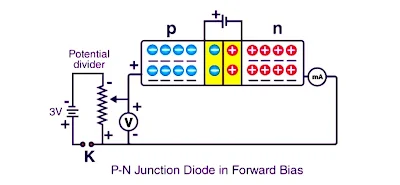
In forward bias, the p-side is connected to the positive terminal and the n-side to the negative terminal of the power supply. This reduces the potential barrier and allows significant current flow once the forward voltage exceeds a certain threshold (~0.7V for silicon).
Reverse Bias:
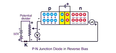
In reverse bias, the p-side is connected to the negative terminal and the n-side to the positive. This increases the barrier, and only a small leakage current (reverse saturation current) flows.
Circuit Diagrams:
Forward Bias:
Reverse Bias:
Procedure:
- Connect the circuit in forward bias mode using the diode, resistor, ammeter, and voltmeter.
- Gradually increase the input voltage in steps (e.g., 0.1V) and record the corresponding current values.
- Note the voltage at which current increases sharply—this is the "knee voltage."
- Now reverse the diode and repeat the experiment in reverse bias mode.
- Record the leakage current values for increasing reverse voltage.
Observation:
1. Table for forward-bias voltage and forward current
| Serial No. of Obs. (1) | Forward-bias Voltage VF (V) (2) | Forward current IF (mA) (3) |
|---|---|---|
| 1. | 0 | 0 |
| 2. | 0.1 | 0 |
| 3. | 0.2 | 0 |
| 4. | 0.3 | 0 |
| 5. | 0.4 | 0.5 |
| 6. | 0.6 | 1 |
| 7. | 0.8 | 2 |
| 8. | 1.0 | 3 |
| 9. | 1.2 | 5 |
| 10. | 1.4 | 7.5 |
| 11. | 1.6 | 10 |
| 12. | 1.8 | 15 |
| 13. | 2.0 | 20 |
| 14. | 2.2 | 25 |
| 15. | 2.4 | 30 |
2. Table for reverse-bias voltage and reverse current
| Serial No. of Obs. (1) | Reverse-bias Voltage VR (V) (2) | Reverse current IR (µA) (3) |
|---|---|---|
| 1. | 0 | 0 |
| 2. | 5.0 | 1 |
| 3. | 7.0 | 2 |
| 4. | 9.0 | 3 |
| 5. | 11.0 | 4 |
| 6. | 13.0 | 5 |
| 7. | 15.0 | 7 |
| 8. | 17.0 | 9 |
| 9. | 19.0 | 11 |
| 10. | 21.0 | 13 |
| 11. | 23.0 | 18 |
| 12. | 25.0 | 25 |
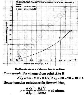
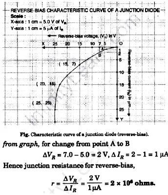
Graph: Plot two graphs
Forward bias: Voltage (X-axis) vs Current (Y-axis) showing exponential rise after.
Reverse bias: Voltage (X-axis) vs Current (Y-axis) showing nearly flat line with very small current.
Result:
Junction Resistance for Reverse bias : $2 \times 10^{6}$ohms
Precaution:
- Ensure correct polarity when connecting the diode.
- Use proper voltage ranges to avoid diode damage.
- Check for zero error in meters before recording readings.


